What is a Calibrated Energy Model?
A Calibrated Energy Model (CEM) is a digital twin of a building created in a thermal modelling tool that is then fed inputs from actual metered data and BMS readings once the building is completed and occupied. This allows the thermal model to be calibrated with the actual installed values for efficiencies, energy use and HVAC component measurements, the model can then be used to predict the impacts of building control changes accurately. It can also highlight ‘problem’ areas in the building and BMS.
Although on more complex projects CEMs can take a lot of work and time to set up they can be extremely useful in testing how suggested renovations or HVAC control changes will perform before these are actually carried out. If we know that the CEM is predicting accurate results by comparing these to meter readings from the actual building, tweaking values in the CEM should give us a good indication of what effects these tweaks would have if carried out on the actual building. This could for example be used to test the effects of updating the VRF system on the CO2 emissions and costs of electricity in the building and thus be used to predict how long the payback period for the upgraded system would be. Another example could be to test how a number of different glazing specifications would perform for a building in need of an update to its façade; the most cost effective option for the long term could then be identified and installed
One New Change Project
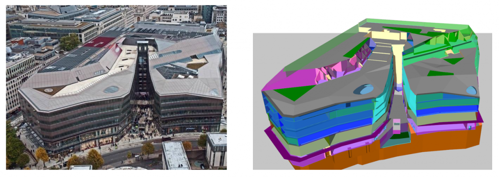
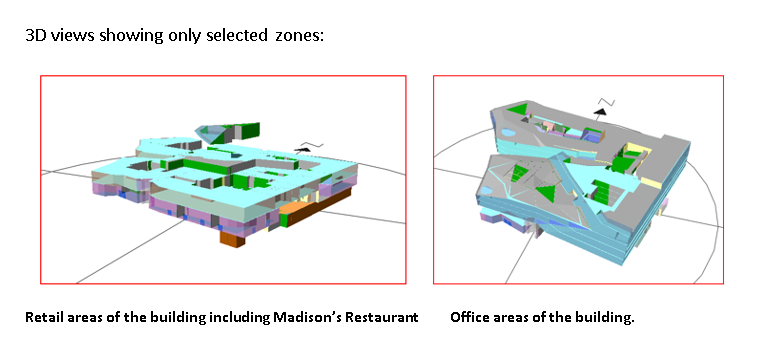
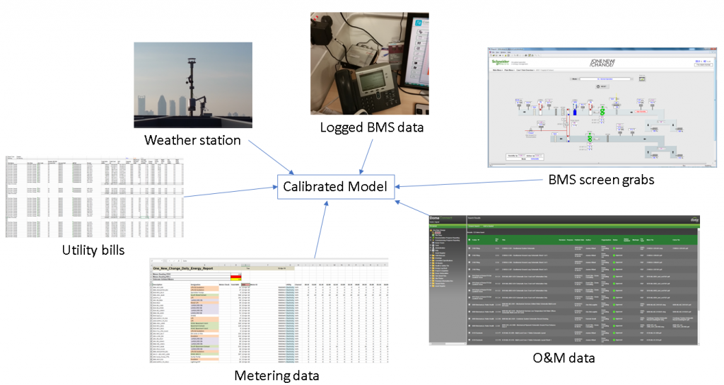
EDSL worked in conjunction with a number of companies including Demand Logic, Landsec and NG Bailey to produce a CEM for the One New Change (ONC) building in London. To start with a 3D model of the building was created and the areas to be included in the analysis were then zoned. There were 2 major areas to be included in the analysis, the offices and the retails areas, with retail being the first two floors, offices above and some restaurant and hospitality on the roof.
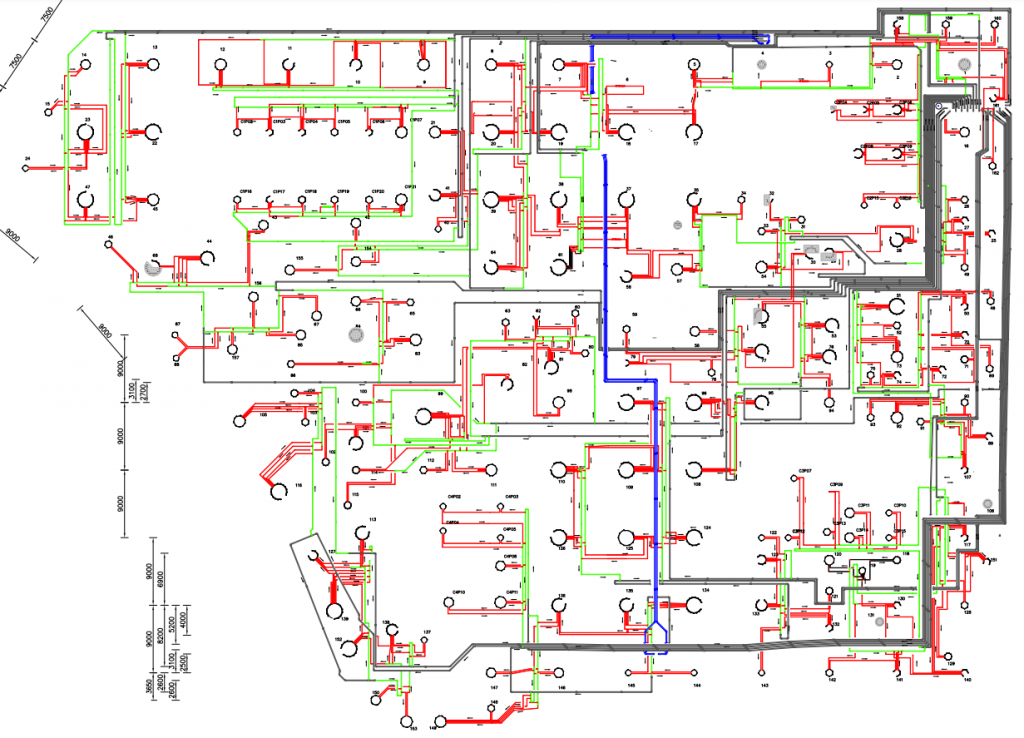
As the building was so large and the HVAC systems utilised a number of different technologies the work on calibrating the systems was time consuming. The building uses 13 Ground Source Heat Pumps (GSHP) for heating and cooling, as shown in the geothermal ground loop pipework layout screenshot below. The water loops for these were set into the underground piles that support the building structurally.
The geothermal ground loop pipework layout schematic for ONC showing the location of all the ground source water loops:
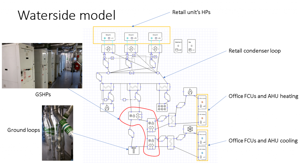
Here is an annotated screenshot of the Tas systems file showing the waterside systems that were set up for the building:
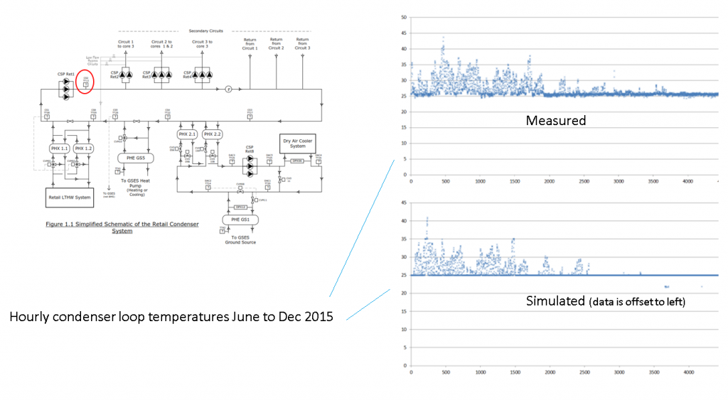
The Retail units were calibrated using the metered data, this allowed for the internal gains to be tweaked over a number of iterations until the model was in good agreement with what was being observed in reality.
A phenomenon seen at ONC from the logged BMS data and meter readings was a substantial amount of simultaneous heating and cooling by the office FCUs in the building. As we were building a CEM this sub-optimal HVAC system behaviour had to be accounted for to compare old and new strategies, both before and after the Energy Conservation Measure (ECM) is implemented. Being able to model simultaneous FCU heating and cooling was an important part of the project.
Simultaneous heating and cooling can happen for a number of reasons. After extensive study of the FCU BMS logged data at ONC, there seemed to be two primary causes for this. Firstly, the control system in the FCUs was not sophisticated enough to control temperatures to the current settings, which were very exacting (effectively trying to control to within 1C, with only a 0.5C deadband). This was termed ‘hunting’ and had been confirmed and explained by the N G Bailey team, who put forward a proposal to cure this issue by widening the deadband.
Secondly, FCU setpoints were varying significantly within zones of the building. This means neighbouring spaces were at different temperatures and this leads to air mixing between these areas due to stack pressure effects. For example a typical FCU on level 4 had the following varying setpoint signal for the year (from 1st January to 11th June 2016).
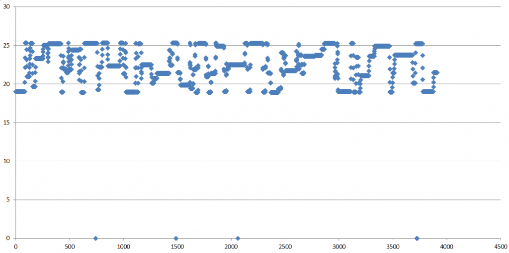
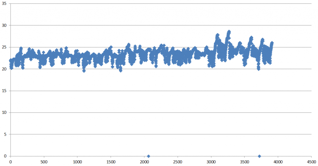
The next chart shows the space/return temperature, so the unit is clearly attempting to follow this erratic setpoint control.
The approach to try and simulate the effect of ‘hunting’ was allowing the heating and cooling to have overlapping control bands. So, for example, heating and cooling control would be as follows.
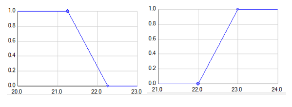
This arrangement gives both heating and cooling between 22C and 22.25C and accounted for the hunting problem quite well. Once the model was calibrated the models simulated results were in agreement with the billing energy information to a fairly accurate degree.
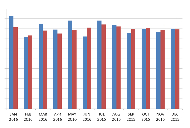
The graph above shows the whole site monthly energy consumptions, the blue bars are the billing information for the building and the red bars are the simulated predictions from the CEM. (Two of the biggest differences can be explained – January billing data included part of December’s usage and June billing information did not include gas usage). The model was then also able to quantify the energy savings following an update on the humidity controls on the HVAC systems for ONC. The model was calibrated around July 2015 and so the July to December results are a better fit than the 2016 results. The building is always changing (so the results drift) which shows a calibrated model needs ‘maintenance’ to keep it up to date.
Implementing an Energy Conservation Measure (ECM) using the CEM
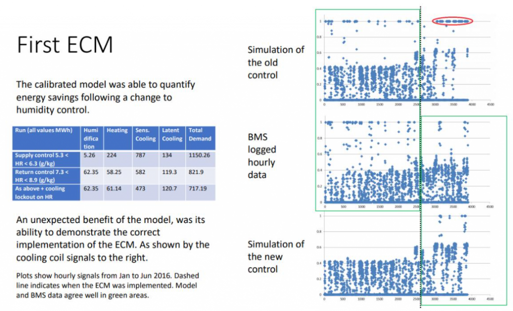
Below is a graphic showing the first ECM implemented at ONC using the CEM, the aim was to include for a change on humidity controls in the building and use the CEM to predict the energy savings from this change. The top left green box shows the original calibrated model performing close to the monitored BMS data. The red lozenge shows how the system would have carried on if the ECM hadn’t been implemented, notice that this includes for a lot of full cooling demand. The bottom right green box shows a Tas model with the ECM in place comparing well to the BMS data after the change, so it’s been implemented correctly and performing as expected. The vertical green line, where the two boxes touch at around April 19th, is when the ECM was introduced. So the lowest graph before the vertical line shows just how much could have been saved had the change been introduced earlier!
The ONC project was highly ambitious due to the sheer size of the building and the complexity of the HVAC systems, with a smaller less complex building the task would be much easier to carry out. A second project at Dashwood House was completed in less than a week. Although creating CEMs for buildings isn’t currently a very commonly undertaken task there may be an increasing need for these in the future, not only are there great benefits in the long run in terms of ensuring building efficiency and saving money on running costs, but as energy targets become more stringent and there is greater responsibility placed on building designers/managers to ensure/prove buildings are performing as efficiently as they’re designed to be. As developments in BMS monitoring and thermal modelling simulation software continue to be made, creating CEMs may become a simpler task to carry out.
If you found this blog interesting you may want to take a look at this somewhat similar article reviewing in use building performance from the November 2020 CIBSE Journal in which the thermal modelling was carried out by Hilson Moran using our software. Tas Systems allowed for the waterside systems to be modelled in great detail.
If you think that you would benefit from having a CEM created for a building contact our Consultancy department for help.

