We will often have to edit the water-side systems created by the wizard. One common reason is to replace a basic setup with a system which has a primary pump loop for the plant equipment, and one or more secondary pump loops distributing water around the building.
Before attempting the setups shown in this guide, you should be familiar with the topic of splitting and recombining plant flows, covered here.
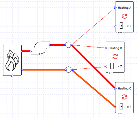
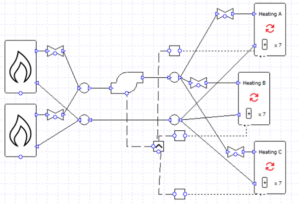
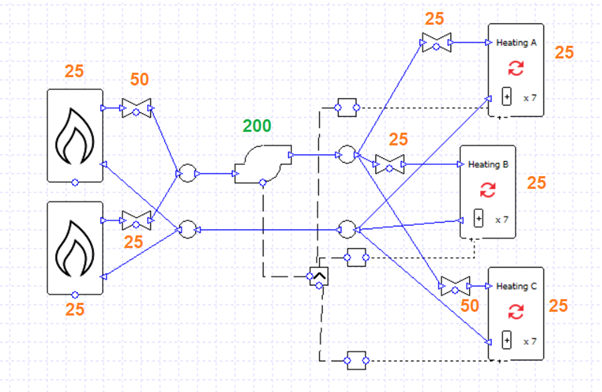
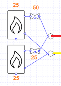
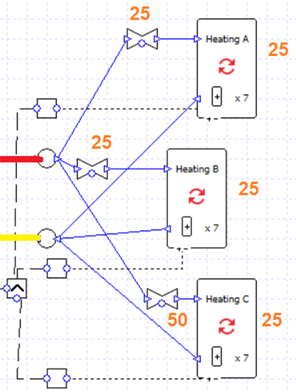
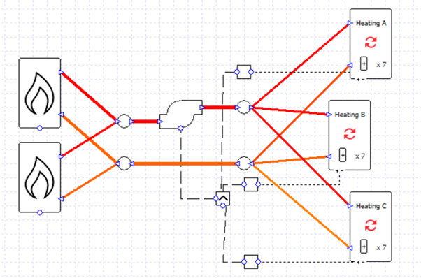
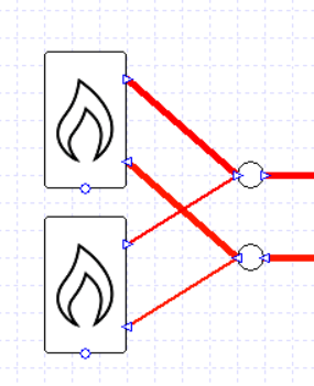
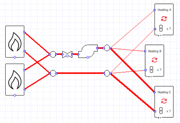
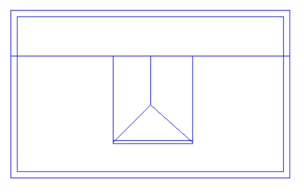
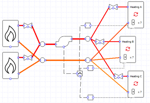
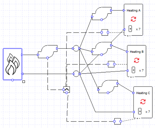
Let’s begin by taking one of the setups from the previous blog post; there are three heating collections and two boilers in parallel.
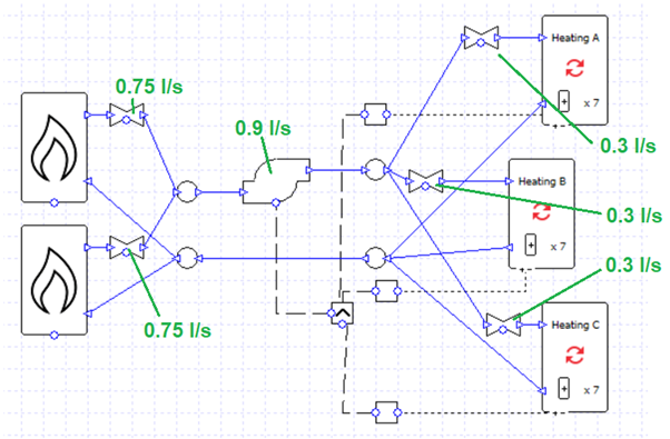
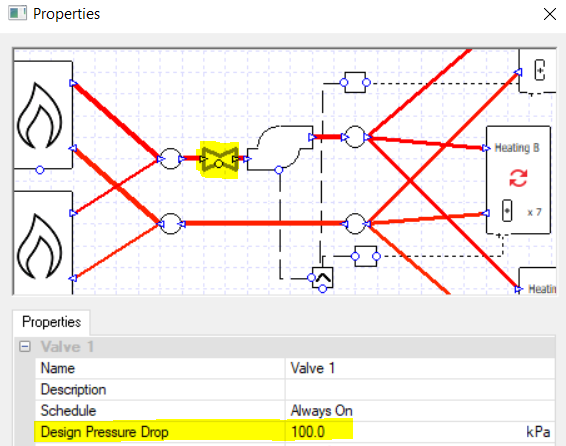
The flow rates are specified rather than sized, and the correct splitting of flows is ensured by the design flow rate entered into the valves.
There is a single pump which is controlled to run when any of the collections has a load.
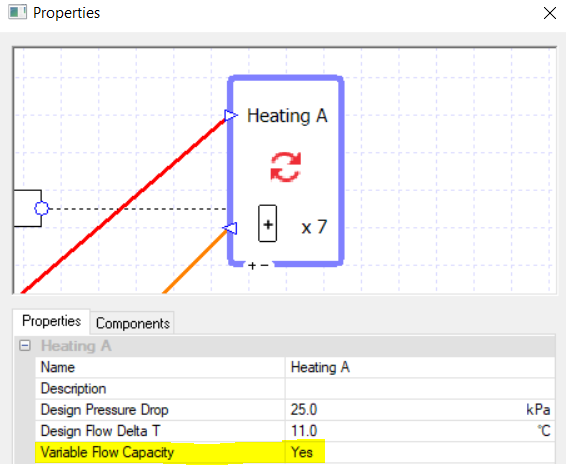
For this starting case, we are not using variable flow capacity on the heating collections.
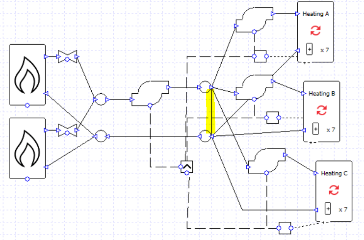
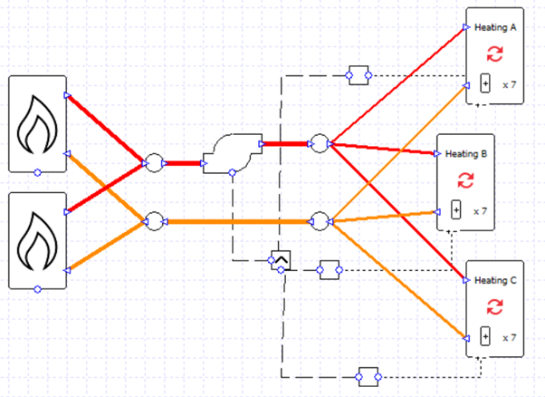
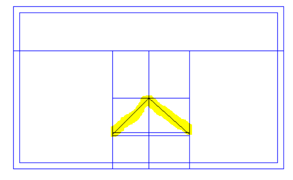
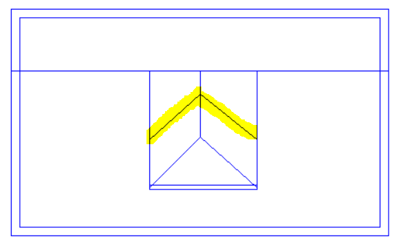
We can very quickly turn this into a primary-secondary setup by replacing the valves with pumps, and adding another pipe (highlighted).
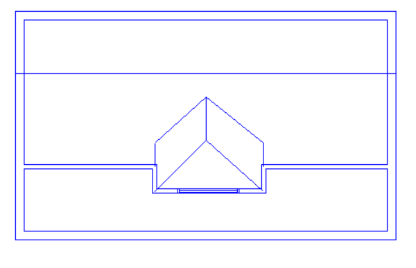
Note that the secondary pumps are connected to the controller of their respective collection. Now each secondary pump will run when its respective collection has a load. The primary pump will run whenever any collection has a load (note the MAX controller).
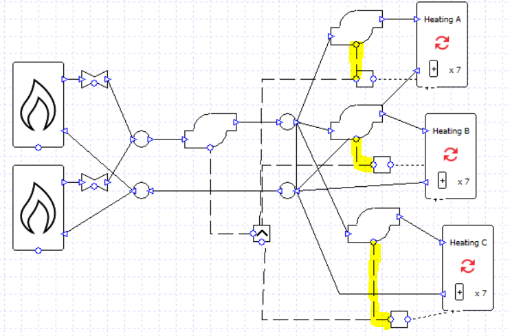
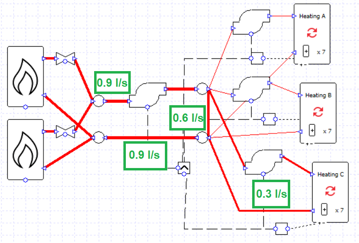
On hours when only one or two collections have a load, any excess flow from the primary pump will be recirculated in the primary loop.
On hours when all the collections have a load, there is no excess flow to recirculate; all of the flow from the primary pump is sent to a collection.
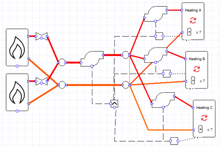
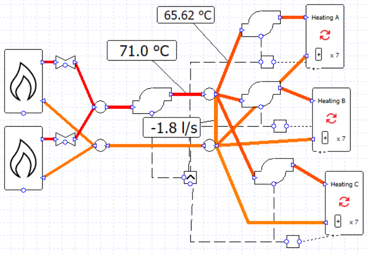
Note that it is possible for the sum of the secondary pump flow rates to exceed the flow rate of the primary pump; to some extent the rules established in the previous blog post do not apply for primary-secondary setups. This is potential pitfall, however, as there is no error message to warn us that the flow rates are unbalanced and we may have water flowing in an unwanted direction, leading to unwanted temperatures. In this image the flow rate of every pump is 0.9 l/s and the water temperature supplied to the collections has fallen below the target of 71 C.
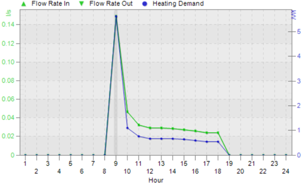
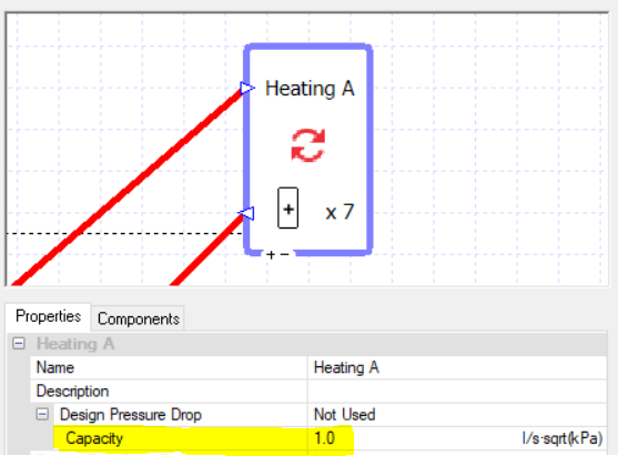
If we return the pump flow rates to the correct values and delete the wires connecting the secondary pumps to their controllers, we can use the variable flow capacity option on the collections.
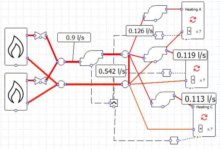
Let’s change how the boilers are used now. Let’s only use both boilers if the required heating load is over 50% of the maximum value.
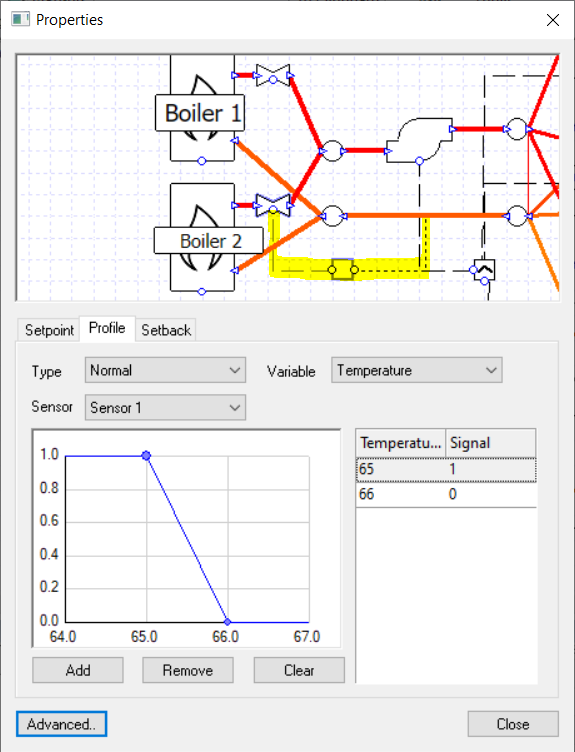
There are a few ways we could detect this switching point; for the sake of this example we are going to test the return water temperature in the primary loop.
We have a setpoint of 71 C and a delta T of 11 C, so for a 50% load we might expect a return temperature of about 65.5 C. Let’s put a controller on the valve of one of the boilers and switch the control signal around this temperature.
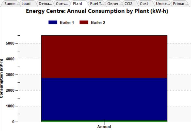
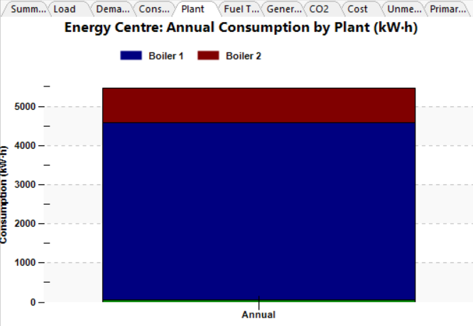
We can soon see the impact on the results, compared to the case where the flow is always split evenly between the boilers.
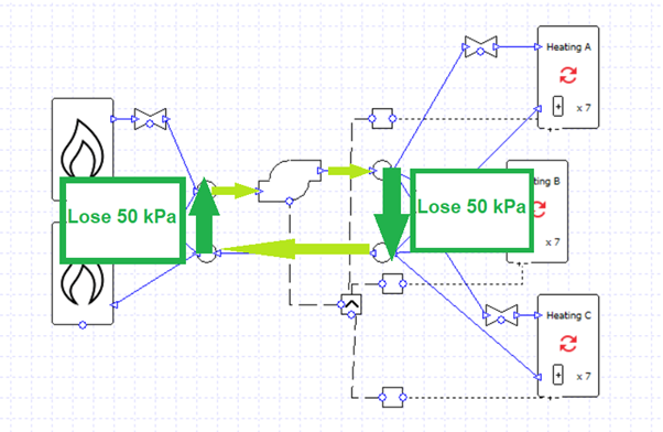
Of course, we could just use a multiboiler component to achieve a similar result instead of two separately controlled boilers. But there may be instances where we prefer to model two separate boilers in this fashion, for example to use a wide control band as in the example above, or in a case where there are further components which we need to take into account (if, for example, one of the boilers was preceded by an exchanger to a different plant loop). There may also be a difference in pump load which needs to be taken into account; on that note, if the boilers and valves are replaced by a multiboiler we should ensure that its pressure drop matches the sum of the pressure drops of the components we have replaced (e.g. 25 kPa for the valve and 25 kPa for the boiler becomes 50 kPa for the multiboiler).
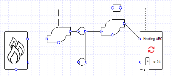
We can try to simplify the setup further; as we are using variable flow capacity on the collections we could experiment with replacing these three collections with a single one and allow the varying flow capacity to provide the flow we need (assuming we don’t need to see the heating load split between the three collections in our results). In this example the difference made to pumping power was around 0.1%, so no major error was introduced; in fact, as simpler systems generally simulate more smoothly and with fewer simulation events, in most situations we are more likely to remove a source of error by simplifying the model.
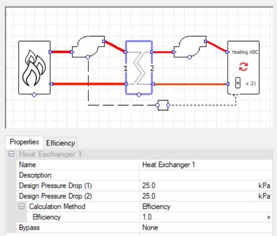
It’s not necessary with such a simple example, but it can sometimes be expedient to separate loops with a 100% efficient exchanger. This is a convenient way to stop pressure and flows from one loop affecting what’s happening in a connected loop, while still conveying 100% of the heat energy as if the water flows were uninterrupted. This is a particularly useful strategy in cases where pressure-related errors are occurring, or errors relating to negative flow through components.
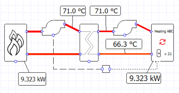
Using this exchanger technique we can make a variation on an earlier setup; two boilers,
this time in series rather than parallel, with the second controlled only to be used for loads over 50% of the peak.
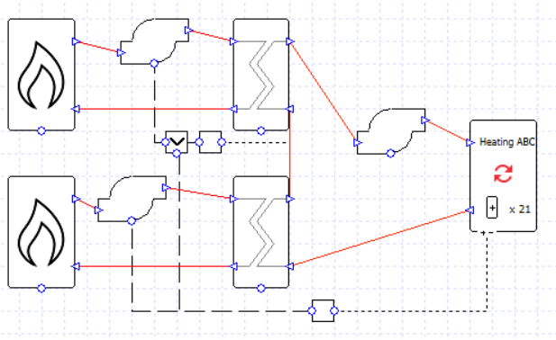
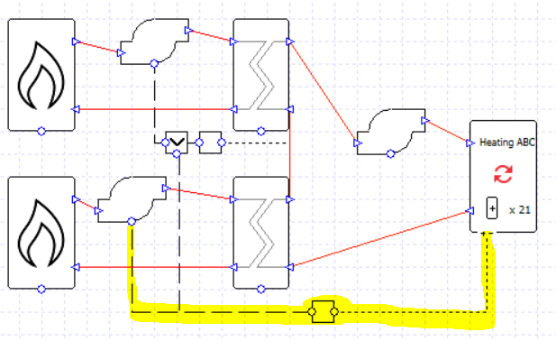
The first boiler in the loop is controlled to be used whenever there is a load at the collection (or rather, its pump is controlled like this, but remember the boiler will only run whenever there is flow through it).
The second boiler is controlled to be used when the water temperature leaving the first boiler is below the setpoint of 71 C, but only on hours when there is a load (note the MIN controller).
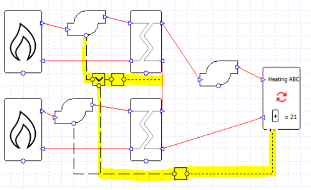
If each boiler is sized for 50% of the total load, and the exchanger efficiency is 100%, then this setup will work just fine. This could be a useful setup if we had a pump associated with each boiler and wanted to see this fact reflected in the results.
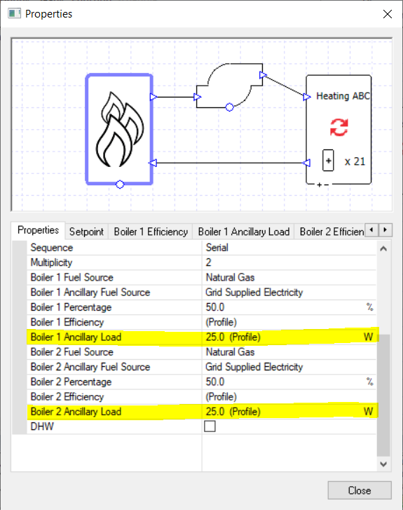
We can take this latest example and change it into a very simple-looking setup.
We have used the ancillary load property to remove the boiler pumps from the schematic and, in effect, absorb them into the multiboiler component.
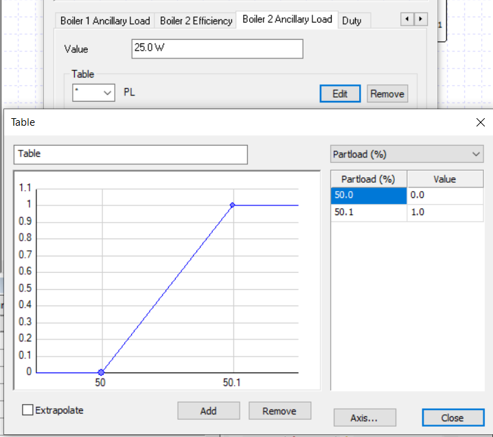
We set the profile modifiers so that ancillary load 1 is used when the heating load is positive, and ancillary load 2 is used when the heating load is over 50%.
If the collection is using variable flow capacity then we don’t even require a controller for the pump.
It is often better to use an elegant solution that gives the correct results, rather than create a complicated setup which matches a schematic drawing. Whether simplification is suitable will depend on the information available and the results detail required, but there are normally several ways to reach similar or even identical results.


