Tag Archives: Tas3D
Drawing Roofs
There are many options for drawing roofs in the Tas3D modeller. This short guide explains when each option may be the best choice and clears up some common questions.
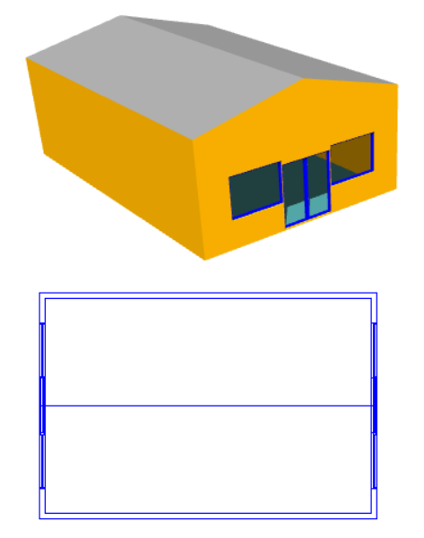
Option 1: Set Wall Height
Pros: A very quick solution for simple sloped roofs with a level ridge.
Cons: Unsuitable for any other type of roof.
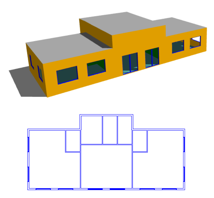
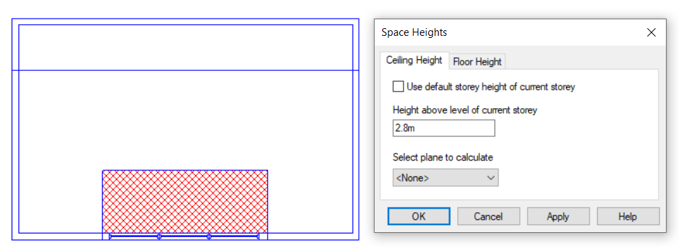
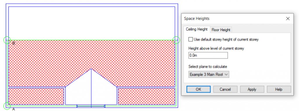
Option 2: Set Space Height
Pros: A very quick solution for stepped flat roofs.
Cons: Unsuitable for sloped roofs.
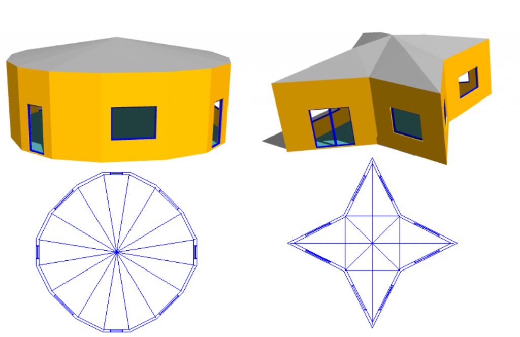
Option 3: Set Point Height (Select Join)
Pros: Allows quick modelling of curved roofs and intersecting slopes.
Cons: Can be time-consuming with roofs that cannot be triangulated easily. Not suitable when there is an abrupt change in roof level.
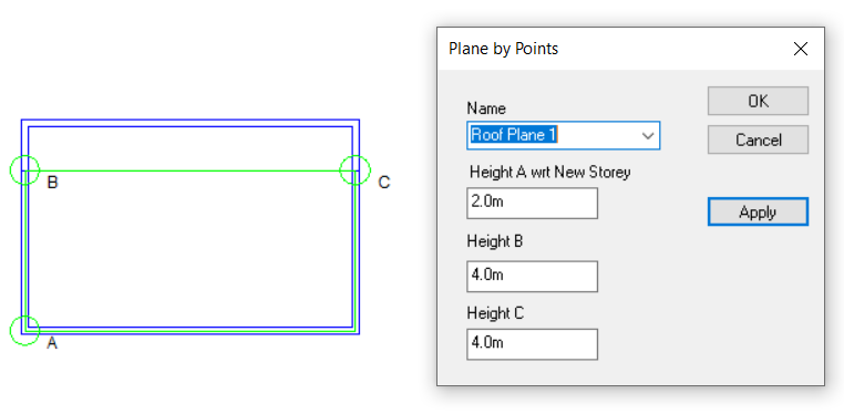
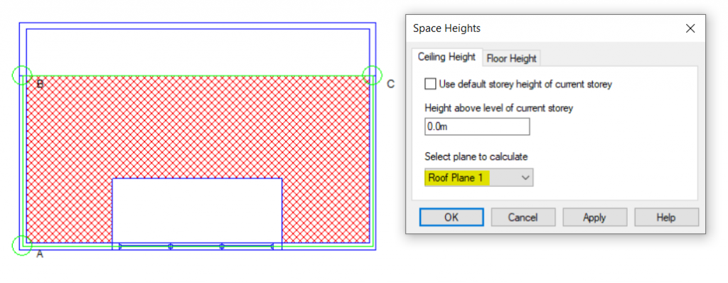
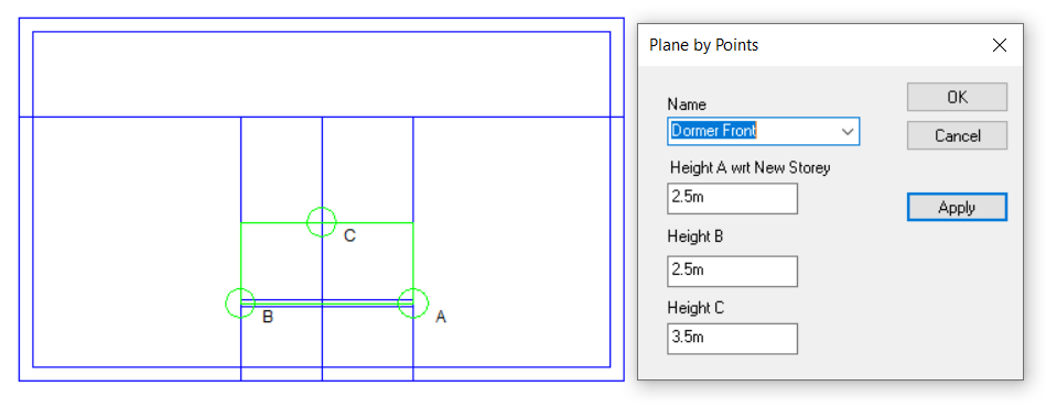
Option 4: Use 3D Planes
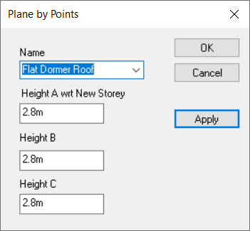
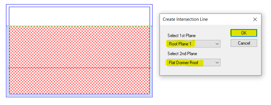
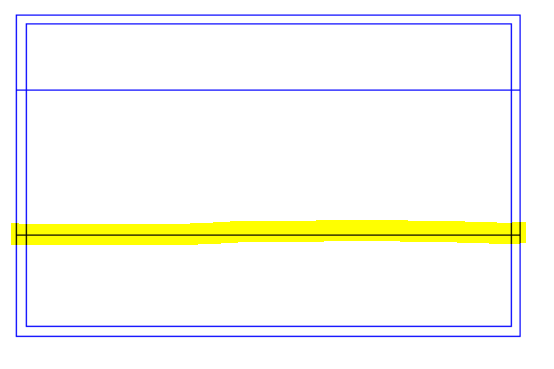
Pros: Can be applied to any sloping roof situation. Plane can be used for multiple roof areas at once. Intersection line between two planes can be calculated automatically. Reduces risk of errors arising from incorrect wall and point heights.
Cons: Creating the planes can be more time-consuming than the other methods.
Examples
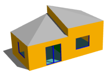
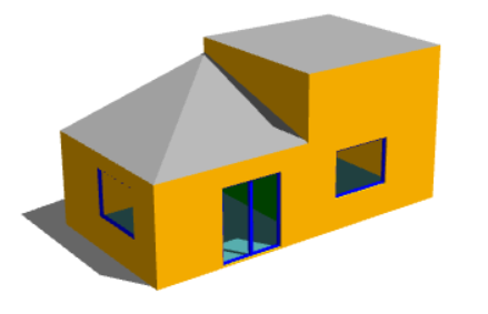
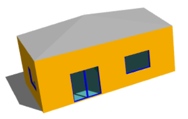
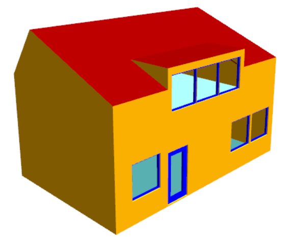
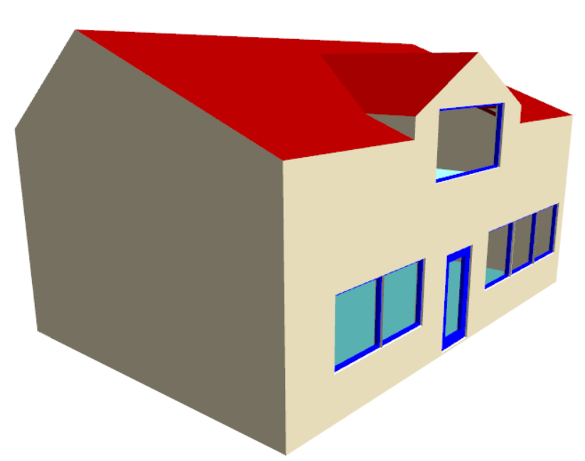
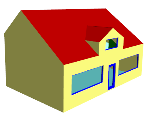
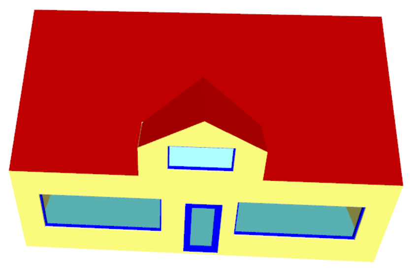
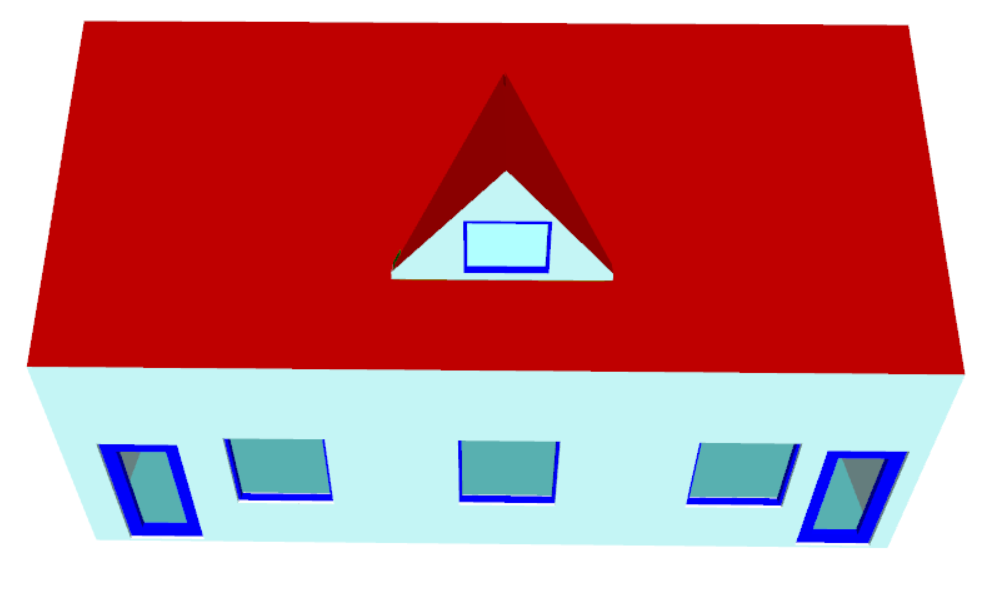
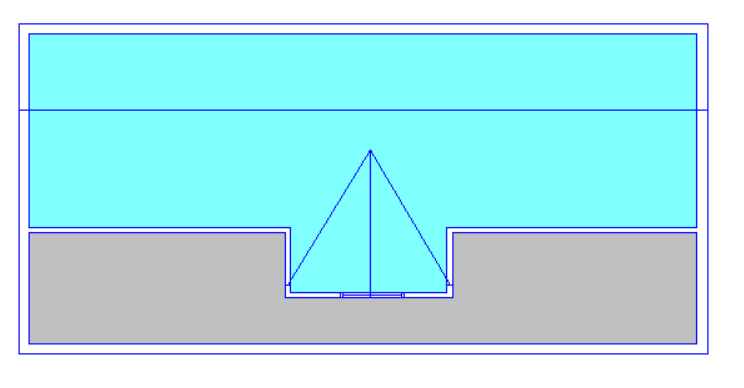
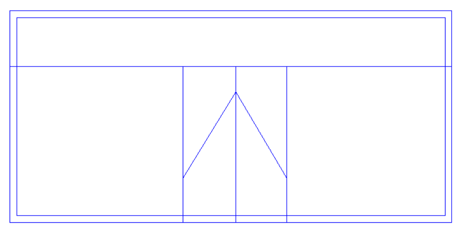
How would three different roofs be modelled most effectively on this simple building?
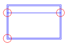
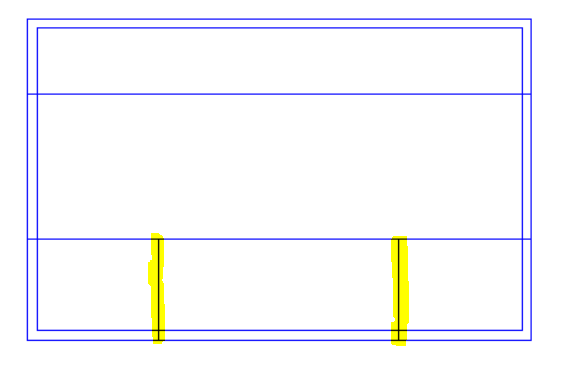
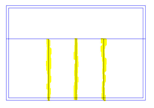
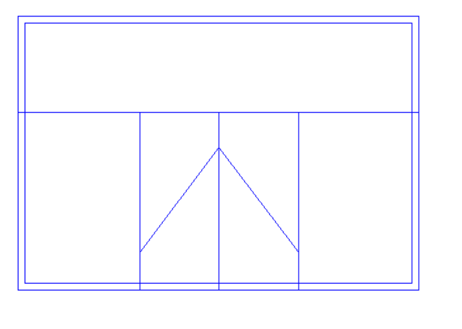
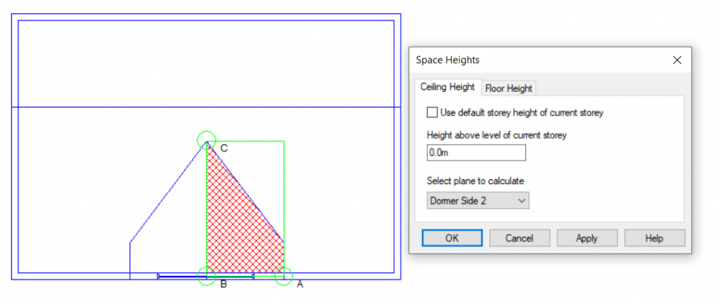
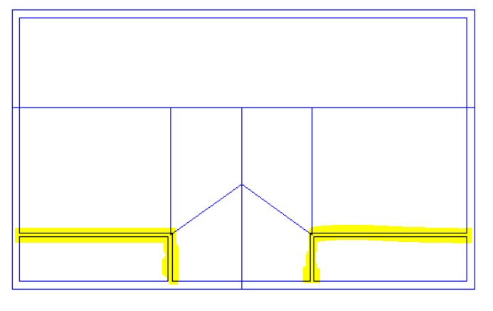
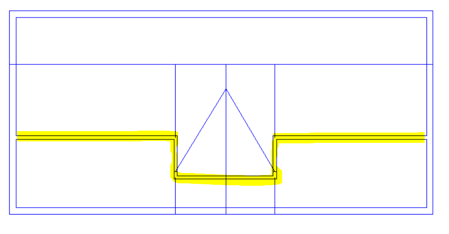
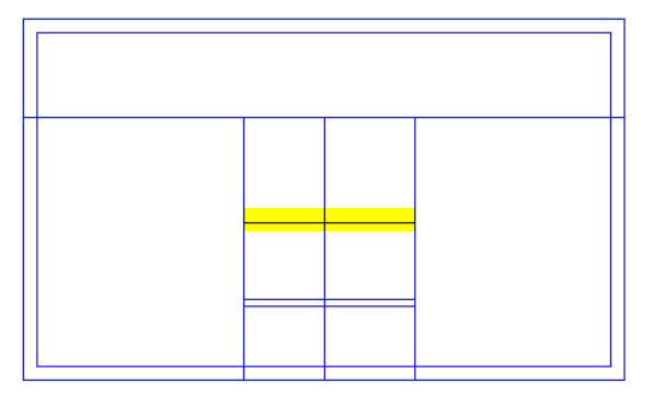
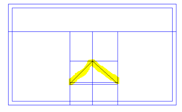
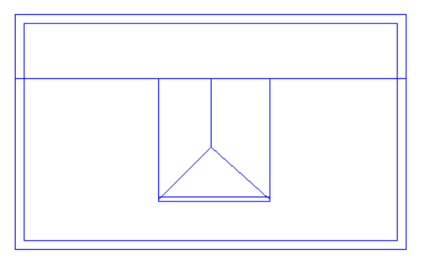
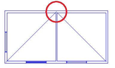
With this roof there is a sudden change in roof level, and the “Set Point Height” option cannot be used. We can see why if we consider one of the points used by both sloping roofs (highlighted in lower image) which would need to have two different roof heights at the same time; in this example it would need to be 4.5m for the left-hand roof and 5.5m for the right-hand roof.
We need to use 3D Planes here.
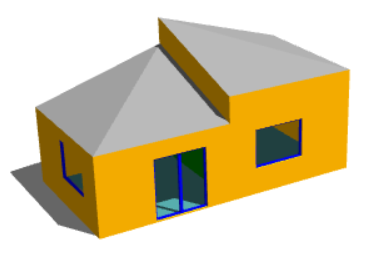
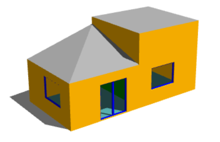
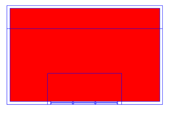
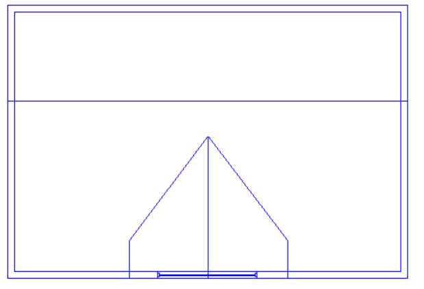
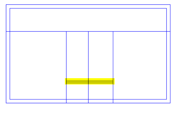
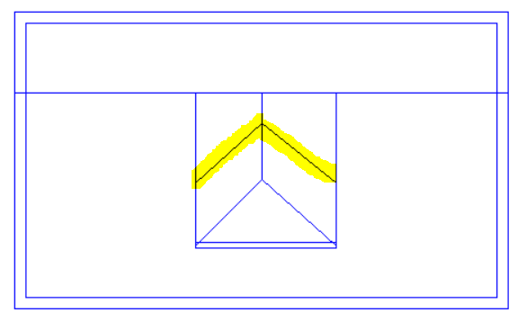
With this example we have a sudden change in roof level, meaning that once again we have points which would need to have two different heights at once; we cannot use the “Set Point Height” option.
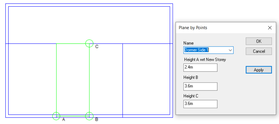
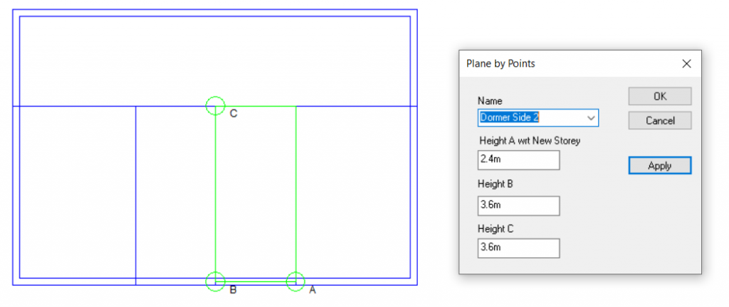
In this case we would need to use 3D Planes for the left-hand roof. For the right-hand roof we can simply use the “Set Space Height” option.
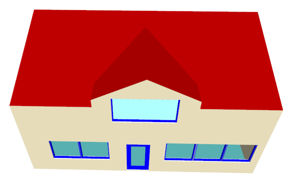
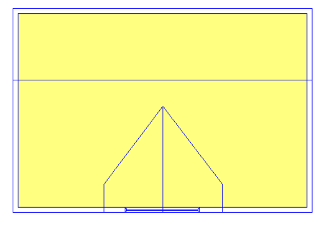
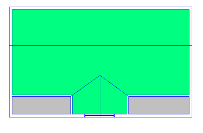
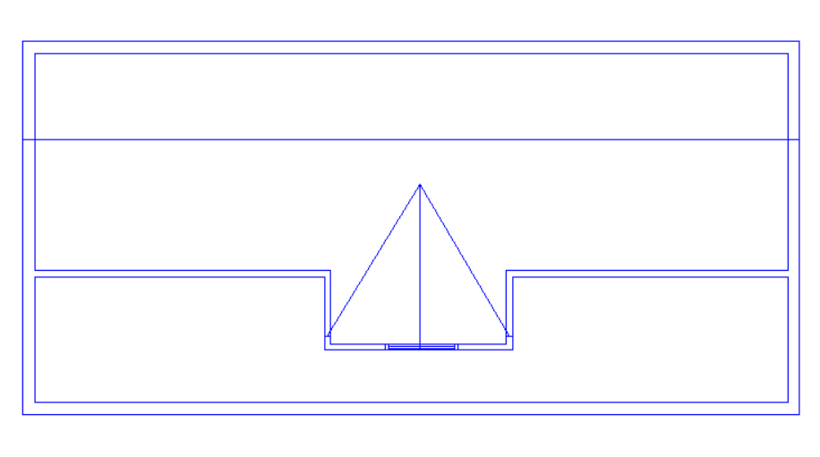
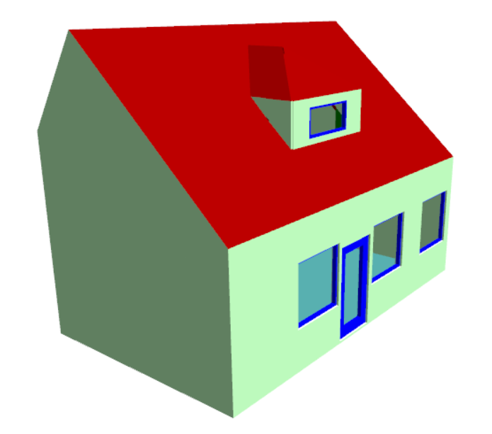
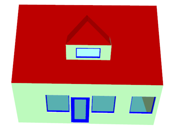
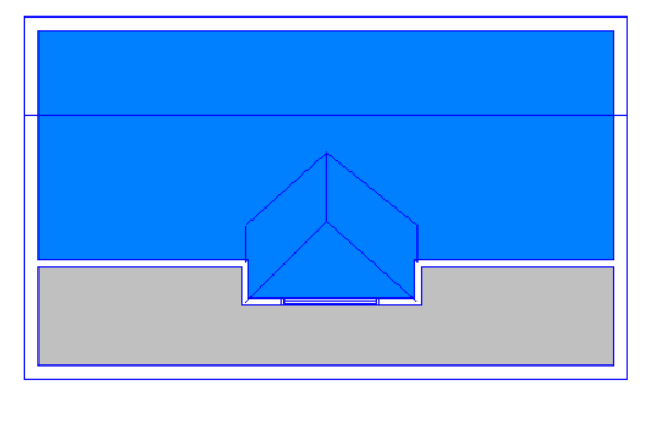
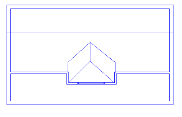
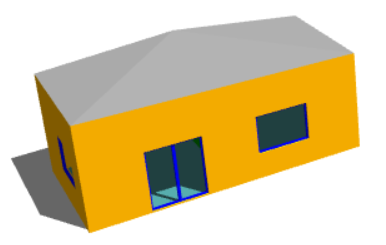
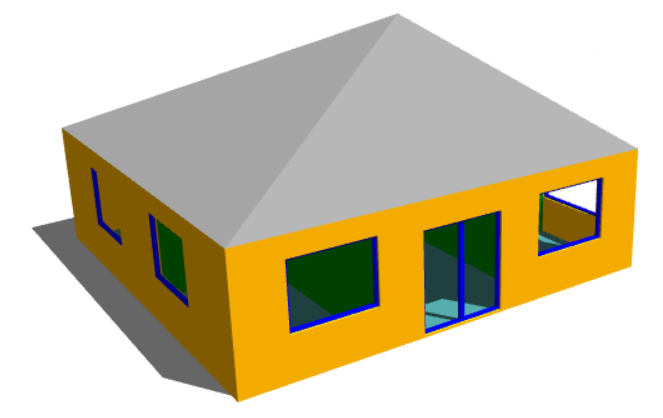
This roof rises to a single point and there is no step or sudden change in roof level. The roof can be achieved easily by using the “Set Point Height” option.
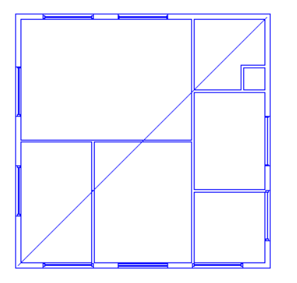
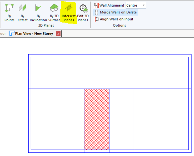
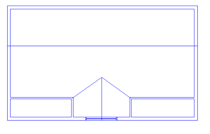
What about a situation where the roof itself is very simple, but there are several internal walls underneath it?
The answer depends on whether or not the roof is on a separate storey. In the case where the internal walls extend upwards to meet the underside of the sloping roof, the best option is to use 3D Planes. But if there is a separate roof space and the internal walls only extend to the underside of a flat ceiling, we should model the roof on a separate storey and the “Set Point Height Option” can be used.
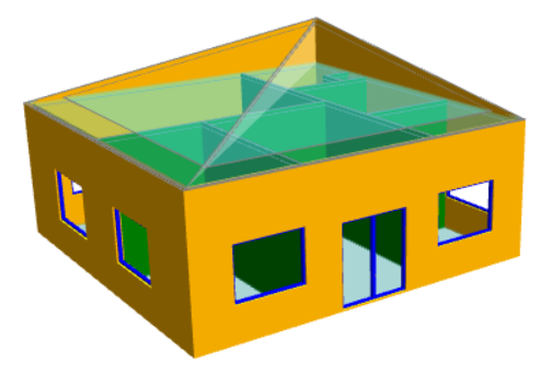
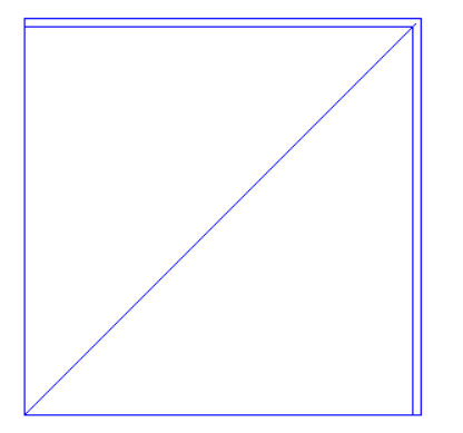
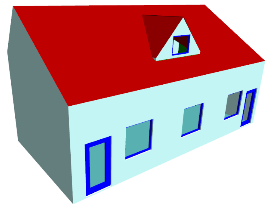
What about “gaps” in the roof where internal walls or null lines are exposed?

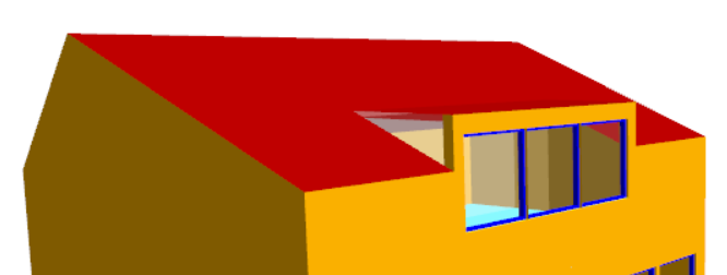
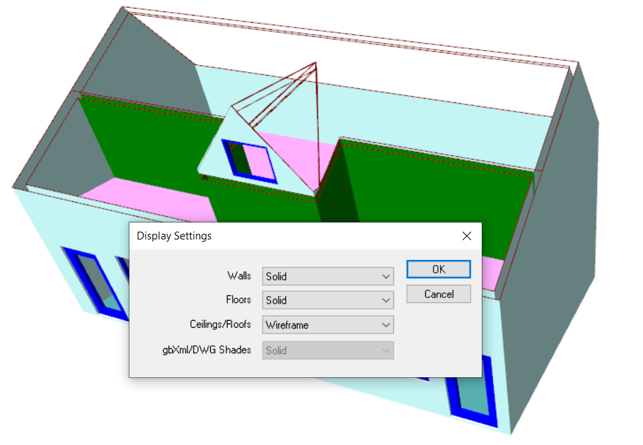
When you create the analysis model, Tas3D creates a new building element for the exposed parts of internal walls, null walls, etc. These new elements, which will have a name ending in “-exposed” can be changed by the user to represent external walls (or, depending on your building, you may want to set these up to represent, e.g., glazing). When you refresh the analysis model you will see that your roof “gaps” have been filled. Be sure to assign an appropriate construction to these building elements in the TBD.

